Engineering reading B / resistance
Frames, walls and shared resistance
Select the response the whole house needs, rather than the component that looks strongest in isolation.
Separate strength, stiffness and ductility
Strength describes resistance to an action. Stiffness describes the relationship between force and deformation. Ductility is the ability to sustain suitable inelastic deformation without an abrupt loss of resistance. These properties are related, but none can stand in for the others. A very stiff system can attract substantial force; a strong system can still allow excessive drift; a nominally ductile material can behave poorly when connections are brittle.
Seismic design commonly anticipates controlled damage under sufficiently strong shaking. The engineer selects a system, applies the governing provisions and details the intended deformation mechanism. The reduction of design forces associated with ductile behaviour is conditional on the required detailing and configuration. It cannot be claimed merely because a house contains steel or timber.
For a homeowner, the choice starts with floor plans, openings, storey heights, material condition and foundation constraints. Discuss performance expectations explicitly: life safety, reduced damage and continued occupancy are different objectives. Higher performance may require additional analysis, cost and coordination, and cannot be guaranteed.
Understand what walls contribute
Timber structural-panel shear walls use sheathing, framing, fasteners and boundary connections as a coordinated assembly. Panel nailing alone does not establish a complete wall. Wall proportions, openings, edge support, hold-downs and anchorage all influence behaviour. The American Wood Council’s Special Design Provisions for Wind and Seismic, or SDPWS, is one relevant US reference where adopted.
Reinforced concrete shear walls can provide substantial stiffness and strength. Their performance depends on reinforcement arrangement, confinement, shear design, coupling and foundation behaviour. ACI 318 is a key US concrete reference, while other jurisdictions use their own standards. Simply thickening a wall is not equivalent to providing suitable seismic detailing.
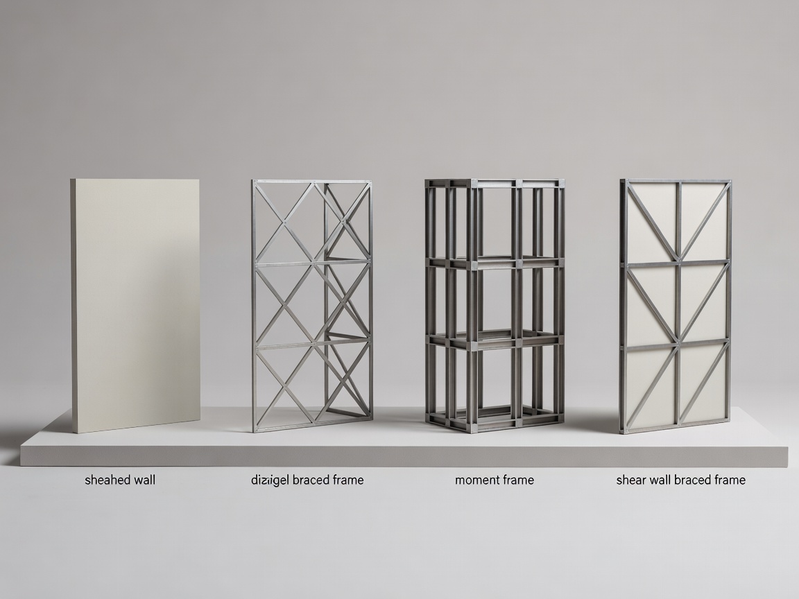
Reinforced masonry walls are another option, but their grouting, reinforcement and anchorage must be established. TMS 402/602 addresses masonry design and construction in relevant US practice. Existing unreinforced masonry should not be treated as equivalent to a modern reinforced system merely because both are made of brick or block.
Understand what frames contribute
Braced frames use diagonal members to carry lateral actions largely through axial forces. Conventional braces may buckle in compression, so the designed mechanism and surrounding members matter. Buckling-restrained braces control brace buckling through a specialist assembly, but they remain engineered products within a complete system rather than universal residential upgrades.
Moment frames resist lateral actions through bending in beams, columns and their connections. They can preserve larger openings, which is useful at garages or glazed façades, but may demand significant foundations and careful drift checks. Connection fabrication and installation can be more demanding than the finished appearance suggests. AISC 341 provides seismic provisions for structural steel buildings in applicable US practice.
Some buildings combine walls and frames. Their force sharing depends on relative stiffness, deformation compatibility and the specific system classification. A formally defined dual system has requirements that go beyond placing a wall beside a frame. The designer must also consider torsion and the interaction between structural and nonstructural components.
| System | Potential fit | Questions to resolve |
|---|---|---|
| Timber shear walls | Distributed resistance in light-frame housing | Available wall lengths, openings, fastening and hold-down routes |
| Concrete or reinforced masonry walls | Stiff resisting elements where mass and foundations are acceptable | Reinforcement, ductile detailing, ground interface and construction quality |
| Braced frames | Defined lateral bays within a coordinated layout | Brace mechanism, gussets, architectural clearance and anchorage |
| Moment frames | Maintaining selected large openings | Drift, joint detailing, fabrication and footing demands |
| Base isolation | Specialist projects with suitable geometry and objectives | Movement clearance, services, access, inspection and ground hazards |
Treat specialist solutions as whole-building choices
Base isolation introduces a designed flexible interface that can reduce certain demands transmitted to the superstructure. It also creates movement requirements around the building and across utilities, stairs and entrances. It does not eliminate earthquakes, ground failure or the need for a properly designed structure above. Existing homes can present difficult access and foundation challenges.
Wellington’s Parliament Buildings in New Zealand provide a documented example of seismic isolation used in an existing complex. The example demonstrates a system principle, not an argument that every house should be isolated. Scale, heritage constraints, performance objectives and engineering resources differ substantially.
Supplemental damping devices dissipate energy through designed mechanisms. Their effectiveness depends on placement, connections and expected movement. A catalogue performance curve cannot establish the response of a particular house. Ask who is responsible for analysis, device specification, installation tolerances and long-term inspection.